Processor Integration
Interface models, matched Rocket packages, execution, and validation scope.
Purpose and supported platform
Processor integration connects an instruction’s generated hardware to the processor that executes its software. APS exports the accelerator RTL and Chipyard configuration from shared inputs so interface capacities, ports, and CSR bindings remain consistent. The current native configuration exporter supports RoCC, RV32, one core.
Chipyard provides the Rocket system around the accelerator: processor execution, instruction dispatch, and the memory connection. Spike + Verilator co-simulation provides a separate, lighter path for checking compiled software against accelerator RTL.
Why memory interfaces matter
Adding arithmetic parallelism does not guarantee application speedup. A sequence of small memory requests can spend more time transferring operands than computing, and a wider interface may support more efficient bursts. Outstanding-request capacity and request order also affect when useful data becomes available. The paper’s interface example illustrates why both interface choice and transaction scheduling belong in accelerator design.
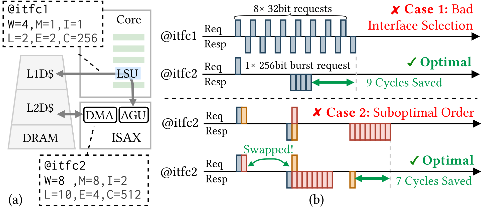
APS models these interface capabilities during synthesis and generates the corresponding scratchpads and adapters. The numerical cycle differences in the figure describe its illustrative example, not a performance claim for every generated design.
Platform configuration
examples/interface.json is a complete starting configuration. It describes the CPU-facing and burst memory interfaces, the Rocket target, and optional CSR bindings.
| Configuration field | Meaning |
|---|---|
width |
Bytes transferred per beat |
min_beats, min_write_beats, max_beats |
Legal transfer sizes |
inflight |
Maximum outstanding transactions |
read_latency, write_completion |
Timing assumptions used by synthesis |
cache_line, cache_hint |
Cache-line size and warm/cold model assumption |
chipyard |
Backend, architecture, core count, and generated module identity |
csrs |
Explicit CSR configuration when needed |
The native CPU interface uses one 4-byte beat; the burst interface uses 8-byte beats with up to 16 beats per transaction and two inflight channels. Use the supplied configuration as the basis for a supported platform. Invalid or conflicting models fail validation rather than silently selecting another platform.
These timing fields guide generated hardware and scheduling; they do not measure actual cache or interconnect performance.
Generate matching RTL and configuration
First obtain functional MLIR through hardware synthesis or the selected ScaleISA path. For the bundled synthesis input:
pixi run build/tools/aps-opt/aps-e2e \
  -i build/quickstart/v3ddist_vv.mlir \
  --export sv -o build/quickstart/v3ddist_vv.sv \
  --interface-config examples/interface.json \
  --chipyard-config build/quickstart/v3ddist_vv.chipyard.yaml
Platform export requires SystemVerilog output to a named file. The configuration is emitted after successful lowering/export. Without an explicit --chipyard-config, its default path replaces the RTL file extension with .chipyard.yaml. Regenerate the package if the checkout moves because the configuration contains the generated RTL path.
Rocket execution
Run pixi run setup-chipyard during installation. Supply a linked RISC-V executable generated for the same instruction and platform; the compilation guide describes the Megg and ScaleISA paths.
For the bundled program and matching generated package:
pixi shell
cd thirdparty/chipyard/sims/verilator
make CONFIG=APSRocketConfig \
  APS_CONFIG="$APS/build/quickstart/v3ddist_vv.chipyard.yaml" \
  run-binary-debug BINARY="$APS/build/quickstart/v3ddist_vv.riscv" LOADMEM=1
APS_CONFIG selects the generated package, while BINARY supplies the linked program. Use absolute paths when entering the simulation directory. Check the program’s reference comparison as well as successful simulator completion.
Functional co-simulation
aps-cosim executes a RISC-V program using Spike and services its custom instructions with a Verilator accelerator model. It checks instruction results, memory effects, CSR transport, and completion without elaborating the full Rocket system.
The Pixi cosim-run task accepts a matching executable and RTL file. It additionally requires Verilator and the configured Spike libraries; designs using CSRs need the appropriate registered bindings. For an integrated ScaleISA run, --emit=elf with supplied runtime/linkage and --cosim lets the driver derive bindings from its hardware export.
Co-simulation’s memory bridge does not reproduce Rocket caches or TileLink performance. Use it for functional behavior and accelerator statistics; use full Rocket simulation when measuring processor cycles.
Validation and measurement
Compare accelerator results against an independent software reference, with input provenance and a defined measured region. Keep these quantities distinct:
| Evidence | What it describes |
|---|---|
| Selection-model estimates | Predicted costs used to choose instructions and implementations |
| Accelerator invocation cycles | Cycles spent executing accelerator commands |
| Rocket processor cycles | Application execution on the configured full processor system |
| Physical timing and area | Technology-specific implementation results |
A requested scheduling clock is not a measured physical frequency. FPGA and ASIC deployment require the target-specific Chipyard flow and board/process configuration in addition to the generated package.